Einthoven's triangle construction. Electrocardiographic leads
11749 0
ECG is an indispensable method for diagnosing disorders heart rate and conduction system of the heart, ventricular and atrial myocardial hypertrophy, coronary artery disease, myocardial infarction and other heart diseases. Detailed description of theoretical ECG basics, the mechanisms of formation of ECG changes in the above diseases and syndromes are given in numerous modern manuals and monographs on ECG (V. N. Orlov, V. V. Murashko; A. V. Strutynsky, M. I. Kechker; A. Z. Chernov , M. I. Kechker, A. B. de Luna, F. Zimmerman, M. Gabriel Hahn, etc.). In this guide, we will limit ourselves to brief information about the methodology and technique of the traditional 12-lead ECG, the principles of ECG analysis, and criteria for diagnosing ECG syndromes and heart disease.
Electrocardiographic leads
An ECG is a recording of fluctuations in the potential difference that occurs on the surface of the myocardium or in its surrounding conductive medium during the propagation of an excitation wave through the heart. An ECG is recorded using an electrocardiograph - a device designed to record changes in the potential difference between two points in the electric field of the heart (for example, on the surface of the body) during its excitation. Modern electrocardiographs are distinguished by technical excellence and the ability to record single-channel and multi-channel ECG. Changes in the potential difference on the surface of the body that occur during the work of the heart are recorded using various ECG lead systems. Each lead registers the potential difference between two points (electrodes) of the electric field of the heart. The electrodes are connected to the electrocardiograph galvanometer. One of the electrodes is connected to the positive pole of the galvanometer (this is the positive or active lead electrode), the second - to its negative pole (negative or indifferent lead electrode). AT clinical practice The 12-lead ECG is widely used. Registration of their indicators is mandatory for each ECG. Register:
- 3 standard leads;
- 3 reinforced unipolar limb leads;
- 6 chest leads.
Standard bipolar leads, proposed in 1913 by Einthoven, fix the potential difference between two points of the electric field, remote from the heart and located in the frontal plane (electrodes on the limbs). To record the leads, the electrodes are placed on the right hand (red marking), left hand(yellow marking) and left leg (green marking) (Fig. 1).
Rice. 1. Scheme of the formation of three standard electrocardiographic leads from the limbs. Below - Einthoven's triangle, each side of which is the axis of one or another standard lead
The electrodes are connected in pairs to the electrocardiograph to register each of the three standard leads. The fourth electrode is placed on the right leg to connect the ground wire (black marking). Standard limb leads are recorded by connecting electrodes in pairs as follows:
- Lead I - left hand (+) and right hand (-);
- Lead II - left leg (+) and right arm (-);
- Lead III - left leg (+) and left arm (-).
Signs (+) and (-) indicate the corresponding connection of the electrodes to the positive or negative poles of the galvanometer, that is, the positive and negative poles of each lead are indicated. The three standard leads form an equilateral triangle (Einthoven's triangle). Its tops are electrodes mounted on right hand, left arm and left leg. In the center of Einthoven's equilateral triangle is the electrical center of the heart, or a single point cardiac dipole, equally distant from all three standard leads. A hypothetical line connecting two electrodes of the same electrocardiographic lead is called the lead axis. The standard lead axes are the sides of Einthoven's triangle. Perpendiculars, lowered from the electrical center of the heart to the axis of each standard lead, divide each axis into two equal parts: positive, facing the positive (active) electrode (+) lead, and negative, facing the negative electrode (-).
Amplified limb leads were proposed by Goldberger in 1942. They record the potential difference between the active positive electrode of a given lead, mounted on the right arm, left arm, or left leg, and the average potential of the other two limbs (Fig. 2).

Rice. 2. Scheme of the formation of three reinforced unipolar limb leads. Below - Einthoven's triangle and the location of the axes of three reinforced unipolar limb leads
Thus, the role of the negative electrode in these leads is played by the so-called combined Goldberger electrode, formed by connecting two limbs through additional resistance. Three enhanced unipolar limb leads are designated as follows:
- aVR - enhanced abduction from the right hand;
- aVL - enhanced abduction from the left hand;
- aVF - enhanced abduction from the left leg.
The designation for augmented limb leads is the abbreviation English words, meaning: (a) - augemented (reinforced); (V) - voltage (potential); (K) - right (right); (L) - left (left); (F) - foot (leg). As seen in fig. 2, the axes of reinforced unipolar limb leads are obtained by connecting the metric center of the heart to the site of application of the active electrode of this lead, that is, to one of the vertices of Einthoven's triangle. The electrical center of the heart divides the axes of these leads into two equal parts: positive, facing the active electrode, and negative, facing the combined Goldberger electrode.
Standard and enhanced unipolar limb leads record changes in the electromotive force of the heart in the frontal plane, that is, in the plane of Einthoven's triangle. For accurate and visual determination of various deviations of the electromotive force of the heart in the frontal plane, a six-axis coordinate system was proposed (Bailey, 1943). The axes of three standard and three enhanced limb leads, drawn through an electric heart meter, form a six-axis coordinate system. The electrical center of the heart divides the axis of each lead into a positive and negative part, facing the active (positive) or negative electrode, respectively (Fig. 3).

Rice. 3. Six-axis coordinate system according to Bailey
Electrocardiographic deviations in limb leads are considered as different projections of the same electromotive force of the heart on the axis of these leads. Thus, by comparing the amplitude and polarity of the electrocardiographic complexes in the leads that are part of the six-axis coordinate system, it is possible to accurately determine the magnitude and direction of the electromotive force vector of the heart in the frontal plane. The direction of the lead axes is determined in degrees. The origin is taken as a radius drawn strictly horizontally from the electrical center of the heart to the left towards the positive pole of the I standard lead. The positive pole of standard lead II is at +60°, aVF at +90°, standard lead III at +120°, aVL at -30°, and aVR at -150° to the horizontal. The aVL axis is perpendicular to the standard lead axis II, the standard lead axis I is perpendicular to the aVF axis, and the aVR axis is perpendicular to the standard lead axis III.
Chest unipolar leads, proposed by Wilson in 1934, register the potential difference between an active positive electrode installed at certain points on the surface of the chest, and Wilson's negative combined electrode (Fig. 4).

Rice. 4. Places of application of 6 chest electrodes
It is formed by a combination of additional resistances of three limbs (right arm, left arm and left leg) with a combined potential close to zero (about 0.2 mV). To record an ECG, active electrodes are installed in 6 generally accepted positions on chest:
- lead V1 - in the fourth intercostal space along the right edge of the sternum;
- lead V2 - in the fourth intercostal space along the left edge of the sternum;
- lead V3 - between the second and fourth police, approximately at the level of the fifth rib along the left parasternal line;
- lead V4 - in the fifth intercostal space along the left mid-clavicular line;
- lead V5 - at the same horizontal level as V4, along the left anterior axillary line;
- lead V6 - along the left mid-axillary line at the same horizontal level as the electrodes of leads V4 and V5.
Unlike standard and augmented limb leads, chest leads record changes in the electromotive force of the heart in the horizontal plane. The line connecting the electrical center of the heart with the location of the active electrode on the chest forms the axis of each chest lead (Fig. 5). The axes of leads V1 and V5, as well as V2 and V6, are approximately perpendicular to each other.

Rice. 5. Location of the axes of 6 chest electrocardiographic leads in the horizontal plane
The diagnostic capabilities of the ECG can be extended with the help of additional leads. Their use is especially advisable in cases where the usual program for recording 12 generally accepted ECG leads does not allow diagnosing a particular pathology, or it is required to clarify the quantitative parameters of the detected changes. The method of registration of additional chest leads differs from the method of recording 6 conventional chest leads by the localization of the active electrode on the surface of the chest. The role of the electrode connected to the negative pole of the cardiograph is played by the combined Wilson electrode. For a more accurate diagnosis of focal myocardial changes in the posterior basal regions of the left ventricle, unipolar leads V7-V9 are used. Active electrodes are placed along the posterior axillary (V7), scapular (V8) and paravertebral (V9) lines at the horizontal level of the V4-V6 electrodes (Fig. 6).

Rice. Fig. 6. The location of the electrodes of additional chest leads V7 - V9 (a) and the axes of these leads in the horizontal plane (b)
For the diagnosis of focal changes in the myocardium of the posterior, anterolateral and upper parts of the anterior wall, bipolar leads along the Sky are used. To record these leads, electrodes are used to record three standard limb leads. A red-marked electrode, usually placed on the right arm, is placed in the second intercostal space along the right edge of the sternum; the electrode from the left leg (green marking) is moved to the position of the chest lead V4, (near the apex of the heart); an electrode with a yellow marking, installed on the left arm, is placed at the same horizontal level as the green electrode, but along the posterior axillary line (Fig. 7). If the electrocardiograph lead switch is in position I of the standard lead, record the lead. By moving the switch to standard leads II and III, the leads (Inferior, I) and (Anterior, A) are recorded respectively. Leads V38-V68 are used to diagnose hypertrophy of the right heart and focal changes in the pancreas. Their active electrodes are placed on the right half of the chest (Fig. 8).

Rice. 7. Location of electrodes and axes of additional chest leads according to the Sky

Rice. 8. Location of electrodes of additional chest leads V38 - V68
Strutynsky A.V.
Electrocardiography
Analysis of electrocardiograms
The human heart is a powerful muscle. With synchronous excitation of the fibers of the heart muscle, a current flows in the environment surrounding the heart, which even on the surface of the body creates a potential difference of several mV. This potential difference is recorded when recording an electrocardiogram. The electrical activity of the heart can be simulated using a dipole electrical generator.
The dipole concept of the heart underlies Einthoven's lead theory, according to which the heart is a current dipole with a dipole moment R s(electric vector of the heart), which rotates, changes its position and point of application during the cardiac cycle (Fig. 34).
According to Einthoven, the heart is located in the center of an equilateral triangle, the vertices of which are: the rightarm - left arm - left leg (Fig. 35 a).
The potential differences taken between these points are the projections of the dipole moment of the heart on the sides of this triangle:
These potential differences, since the time of Einthoven in physiology, have been called "leads". Three standard assignments are resulted on fig. 35 b. vector direction R s determines the electrical axis of the heart.

Rice. 35 a.

Rice. 35 b. Normal ECG in three standard leads

Rice. 35th c. Prong R- atrial depolarization
QRS- ventricular depolarization T– repolarization
The line of the electrical axis of the heart, when crossing with the direction of the 1st lead, forms an angle that determines the direction of the electrical axis of the heart (Fig. 35 b). Since the electrical moment of the heart-dipole changes with time, then in the leads, the dependences of the potential difference on time, which are called electrocardiograms, will be obtained.
Axis O is the axis of zero potential. Three characteristic teeth are noted on the ECG P, QRS, T(designation according to Einthoven).
The heights of the teeth in various leads are determined by the direction of the electrical axis of the heart, i.e. angle (Fig. 35 b). The highest teeth in the second lead, the lowest in the third. By comparing the ECG in three leads in one cycle, they form an idea of the state of the neuromuscular apparatus of the heart (Fig. 35 c).
Factors affecting the ECG
The position of the heart. The direction of the electrical axis of the heart coincides with the anatomical axis of the heart. If the angle is between 40° and 70°, this electrical axis position is considered normal. The ECG has the usual ratio of teeth in I, II, III standard leads. If it is close or equal to 0°, then the electrical axis of the heart is parallel to the line of the first lead and the ECG is characterized by high amplitudes in lead I. If close to 90°, the amplitudes in lead I are minimal. Deviation of the electrical axis from the anatomical one in one direction or another clinically means unilateral myocardial damage.
Change in body position causes some changes in the position of the heart in the chest and is accompanied by a change in the electrical conductivity of the media surrounding the heart. If the ECG does not change its shape when the body is moved, then this fact also has diagnostic value.
ECG (electrocardiography, or simply, a cardiogram) is the main method for studying cardiac activity. The method is so simple, convenient, and, at the same time, informative that it is used everywhere. In addition, the ECG is absolutely safe, and there are no contraindications to it.
Therefore, it is used not only for diagnostics cardiovascular diseases, but also as a preventive measure during scheduled medical examinations, before sports competitions. In addition, an ECG is recorded to determine suitability for certain professions associated with heavy physical exertion.
Our heart contracts under the action of impulses that pass through the conduction system of the heart. Each pulse represents an electrical current. This current originates at the site of impulse generation in the sinus node, and then goes to the atria and ventricles. Under the action of the impulse, contraction (systole) and relaxation (diastole) of the atria and ventricles occur.
Moreover, systoles and diastoles occur in a strict sequence - first in the atria (in the right atrium a little earlier), and then in the ventricles. This is the only way to ensure normal hemodynamics (blood circulation) with a full supply of blood to organs and tissues.
Electric currents in the conduction system of the heart create an electric and magnetic field around them. One of the characteristics of this field is the electric potential. With abnormal contractions and inadequate hemodynamics, the magnitude of the potentials will differ from the potentials characteristic of the heart contractions of a healthy heart. In any case, both in the norm and in pathology, the electrical potentials are negligible.
But tissues have electrical conductivity, and therefore the electric field of a beating heart spreads throughout the body, and the potentials can be recorded on the surface of the body. All that is needed for this is a highly sensitive apparatus equipped with sensors or electrodes. If using this device, called an electrocardiograph, to register electrical potentials corresponding to the impulses of the conducting system, then it is possible to judge the work of the heart and diagnose violations of its work.
This idea formed the basis of the corresponding concept developed by the Dutch physiologist Einthoven. At the end of the XIX century. this scientist formulated the basic principles of the ECG and created the first cardiograph. In a simplified form, an electrocardiograph consists of electrodes, a galvanometer, an amplification system, lead switches, and a recording device. Electric potentials are perceived by electrodes, which are superimposed on various parts of the body. The choice of assignment is carried out by means of the switch of the device.
Since the electrical potentials are negligible, they are first amplified and then fed to the galvanometer, and from there, in turn, to the recording device. This device is an ink recorder and paper tape. Already at the beginning of the 20th century. Einthoven was the first to use ECG for diagnostic purposes, for which he was awarded the Nobel Prize.
ECG Einthoven triangle
According to Einthoven's theory, the human heart, located in the chest with a shift to the left, is located in the center of a kind of triangle. The vertices of this triangle, which is called Einthoven's triangle, are formed by three limbs - the right hand, the left hand, and the left foot. Einthoven proposed to register the potential difference between the electrodes applied to the limbs.
The potential difference is determined in three leads, which are called standard, and denoted by Roman numerals. These leads are the sides of Einthoven's triangle. In this case, depending on the lead in which the ECG is recorded, the same electrode can be active, positive (+), or negative (-):
- Left hand (+) - right hand (-)
- Right arm (-) - left leg (+)
- Left hand (-) - left leg (+)
Rice. 1. Einthoven's triangle.
A little later, it was proposed to record enhanced unipolar leads from the extremities - the vertices of the Eithoven triangle. These enhanced leads are designated by the English abbreviations aV (augmented voltage - enhanced potential).
aVL (left) - left hand;
aVR (right) - right hand;
aVF (foot) - left foot.
In reinforced unipolar leads, the potential difference between the limb on which the active electrode is applied and the average potential of the other two limbs is determined.
In the middle of the XX century. The ECG was supplemented by Wilson, who, in addition to standard and unipolar leads, proposed recording the electrical activity of the heart from unipolar chest leads. These leads are denoted by the letter V. In an ECG study, six unipolar leads located on the anterior surface of the chest are used.
Since cardiac pathology, as a rule, affects the left ventricle of the heart, most chest leads V are located in the left half of the chest.

Rice. 2.
V 1 - fourth intercostal space at the right edge of the sternum;
V 2 - fourth intercostal space at the left edge of the sternum;
V 3 - the middle between V 1 and V 2;
V 4 - fifth intercostal space along the midclavicular line;
V 5 - horizontally along the anterior axillary line at the level of V 4;
V 6 - horizontally along the midaxillary line at the level of V 4.
These 12 leads (3 standard + 3 unipolar limb + 6 chest) are mandatory. They are recorded and evaluated in all cases of ECG for diagnostic or prophylactic purposes.
In addition, there are a number of additional leads. They are recorded rarely and for certain indications, for example, when it is necessary to clarify the localization of myocardial infarction, to diagnose hypertrophy of the right ventricle, auricles, etc. Additional ECG leads include chest:
V 7 - at the level of V 4 -V 6 along the posterior axillary line;
V 8 - at the level of V 4 -V 6 along the scapular line;
V 9 - at the level of V 4 -V 6 along the paravertebral (paravertebral) line.
In rare cases, to diagnose changes in the upper parts of the heart, chest electrodes can be located 1-2 intercostal spaces higher than usual. In this case, V 1 , V 2 are denoted, where the superscript reflects how many intercostal spaces the electrode is located above.
Sometimes, to diagnose changes in the right parts of the heart, chest electrodes are placed on the right half of the chest at points that are symmetrical to those in the standard method of recording chest leads in the left half of the chest. In the designation of such leads, the letter R is used, which means right, right - B 3 R, B 4 R.
Cardiologists sometimes resort to bipolar leads, once proposed by the German scientist Neb. The principle of registration of leads in the Sky is approximately the same as the registration of standard leads I, II, III. But in order to form a triangle, the electrodes are applied not to the limbs, but to the chest.
The electrode from the right hand of the hand is placed in the second intercostal space at the right edge of the sternum, from the left hand - along the posterior axillary line at the level of the vane of the heart, and from the left leg - directly to the projection point of the vane of the heart, corresponding to V 4 . Between these points, three leads are recorded, which are denoted by the Latin letters D, A, I:
D (dorsalis) - posterior lead, corresponds to standard lead I, resembles V 7 ;
A (anterior) - anterior lead, corresponds to standard lead II, resembles V 5 ;
I (inferior) - inferior lead, corresponds to the standard lead III, is similar to V 2 .
For the diagnosis of posterior basal forms of infarction, Slopak leads are recorded, denoted by the letter S. When registering Slopak leads, the electrode applied to the left arm is placed along the left posterior axillary line at the level of the apex beat, and the electrode from the right hand is moved alternately to four points:
S 1 - at the left edge of the sternum;
S 2 - along the midclavicular line;
S 3 - in the middle between C 2 and C 4;
S 4 - along the anterior axillary line.
On rare occasions, for ECG diagnostics resort to precordial mapping, when 35 electrodes in 5 rows of 7 in each are located on the left anterolateral surface of the chest. Sometimes electrodes are placed in the epigastric region, advanced into the esophagus at a distance of 30-50 cm from the incisors, and even inserted into the cavity of the heart chambers when probing it through large vessels. But all these specific ECG recording methods are carried out only in specialized centers with the necessary equipment and qualified doctors.
ECG technique
In a planned manner, ECG recording is carried out in a specialized room equipped with an electrocardiograph. In some modern cardiographs, instead of the usual ink recorder, a thermal printing mechanism is used, which, with the help of heat, burns the cardiogram curve onto paper. But in this case, a special paper or thermal paper is needed for the cardiogram. For clarity and convenience of calculating ECG parameters in cardiographs, graph paper is used.
In cardiographs of the latest modifications, the ECG is displayed on the monitor screen, decrypted using the supplied software, and not only printed on paper, but also stored on a digital medium (disk, flash drive). Despite all these improvements, the principle of the device of the ECG recording cardiograph has not changed much since the time it was developed by Einthoven.
Most modern electrocardiographs are multichannel. Unlike traditional single-channel devices, they register not one, but several leads at once. In 3-channel devices, first standard I, II, III are recorded, then reinforced unipolar limb leads aVL, aVR, aVF, and then chest leads - V 1-3 and V 4-6. In 6-channel electrocardiographs, standard and unipolar limb leads are first recorded, and then all chest leads.
The room in which the recording is carried out must be removed from sources of electromagnetic fields, X-ray radiation. Therefore, the ECG room should not be placed in close proximity to the X-ray room, rooms where physiotherapy procedures are performed, as well as electric motors, power panels, cables, etc.
Special preparation before recording an ECG is not carried out. It is desirable that the patient was rested and slept. Previous physical and psycho-emotional stresses can affect the results and are therefore undesirable. Sometimes food intake can also affect the results. Therefore, the ECG is recorded on an empty stomach, not earlier than 2 hours after eating.
During the recording of the ECG, the subject lies on a flat hard surface (on the couch) in a relaxed state. Places for applying electrodes should be free from clothing.
Therefore, you need to undress to the waist, legs and feet free from clothes and shoes. Electrodes are applied to internal surfaces lower thirds shins and feet (inner surface of the wrist and ankle joints). These electrodes have the form of plates and are designed to register standard leads and unipolar leads from the extremities. These same electrodes can look like bracelets or clothespins.
Each limb has its own electrode. To avoid errors and confusion, the electrodes or wires through which they are connected to the device are color-coded:
- To the right hand - red;
- To the left hand - yellow;
- To the left leg - green;
- To the right leg - black.
Why do you need a black electrode? After all right leg is not included in Einthoven's triangle and is not read. The black electrode is for grounding. According to the basic safety requirements, all electrical equipment, incl. and electrocardiographs must be grounded.
To do this, ECG rooms are equipped with a ground loop. And if the ECG is recorded in a non-specialized room, for example, at home by ambulance workers, the device is grounded to a central heating battery or to a water pipe. To do this, there is a special wire with a fixing clip at the end.
Electrodes for registration of chest leads have the form of a pear-suction cup, and are equipped with a wire white color. If the device is single-channel, there is only one suction cup, and it is moved to the required points on the chest.
There are six of these suction cups in multichannel devices, and they are also color-coded:
V 1 - red;
V 2 - yellow;
V 3 - green;
V 4 - brown;
V 5 - black;
V 6 - purple or blue.
It is important that all electrodes fit snugly against the skin. The skin itself should be clean, devoid of sebaceous fat and sweat secretions. Otherwise, the quality of the electrocardiogram may deteriorate. Between the skin and the electrode there are induction currents, or simply, pickup. Quite often, a tip-off occurs in men with thick hair on the chest and on the limbs. Therefore, here it is especially necessary to ensure that the contact between the skin and the electrode is not disturbed. The pickup sharply degrades the quality of the electrocardiogram, on which small teeth are displayed instead of a flat line.

Rice. 3. Flooding currents.
Therefore, the place where the electrodes are applied is recommended to be degreased with alcohol, moistened with soapy water or conductive gel. For electrodes from the extremities, gauze wipes moistened with saline are also suitable. However, it should be borne in mind that saline dries quickly, and contact may be broken.
Before recording, it is necessary to check the calibration of the device. For this, it has a special button - the so-called. control millivolt. This value reflects the height of the tooth at a potential difference of 1 millivolt (1 mV). In electrocardiography, the value of the control millivolt is 1 cm. This means that with a difference in electrical potentials of 1 mV, the height (or depth) of the ECG wave is 1 cm.

Rice. 4. Each ECG recording must be preceded by a control millivolt check.
Recording of electrocardiograms is carried out at a tape speed of 10 to 100 mm/s. True, extreme values are used very rarely. Basically, the cardiogram is recorded at a speed of 25 or 50 mm / s. Moreover, the last value, 50 mm / s, is standard, and most often used. The speed of 25 mm/h is used where it is necessary to register the largest number contractions of the heart. After all, the lower the speed of the tape, the greater the number of contractions of the heart it displays per unit of time.

Rice. 5. The same ECG recorded at 50 mm/s and 25 mm/s.
The ECG is recorded with quiet breathing. In this case, the subject should not talk, sneeze, cough, laugh, make sudden movements. When registering the III standard lead, a deep breath with a short breath hold may be required. This is done in order to distinguish functional changes, which are quite often found in this lead, from pathological ones.
The section of the cardiogram with teeth corresponding to the systole and diastole of the heart is called the cardiac cycle. Usually, 4-5 cardiac cycles are recorded in each lead. In most cases, this is sufficient. However, in case of cardiac arrhythmias, if myocardial infarction is suspected, recording up to 8-10 cycles may be required. To switch from one lead to another, the nurse uses a special switch.
At the end of the recording, the subject is released from the electrodes, and the tape is signed - at the very beginning, the full name is indicated. and age. Sometimes, to detail the pathology or determine physical endurance, an ECG is performed against the background of medication or physical exertion. Drug tests are carried out with various drugs - atropine, chimes, potassium chloride, beta-blockers. Physical exercise are carried out on an exercise bike (veloergometry), with walking on a treadmill, or walking for certain distances. For completeness of information, the ECG is recorded before and after exercise, as well as directly during bicycle ergometry.
Many negative changes in the work of the heart, such as rhythm disturbances, are transient and may not be detected during an ECG recording, even with a large number of leads. In these cases, Holter monitoring is performed - an ECG is recorded according to Holter in continuous mode during the day. A portable recorder equipped with electrodes is attached to the patient's body. Then the patient goes home, where he leads the usual mode for himself. After a day, the recording device is removed and the available data is decoded.
A normal ECG looks something like this:
Rice. 6. Tape with ECG
All deviations in the cardiogram from midline(isolines) are called teeth. The teeth deviated upward from the isoline are considered to be positive, downward - negative. The gap between the teeth is called a segment, and the tooth and its corresponding segment are called the interval. Before finding out what a particular wave, segment or interval is, it is worth briefly dwelling on the principle of forming an ECG curve.
Normally, the heart impulse originates in the sinoatrial (sinus) node of the right atrium. Then it spreads to the atria - first the right, then the left. After that, the impulse is sent to the atrioventricular node (atrioventricular or AV junction), and further along the bundle of His. Branches of the bundle of His or legs (right, left anterior and left posterior) end with Purkinje fibers. From these fibers, the impulse propagates directly to the myocardium, leading to its contraction - systole, which is replaced by relaxation - diastole.
The passage of an impulse along nerve fiber and the subsequent contraction of the cardiomyocyte is a complex electromechanical process during which the values of electrical potentials on both sides of the fiber membrane change. The difference between these potentials is called the transmembrane potential (TMP). This difference is due to the unequal permeability of the membrane for potassium and sodium ions. Potassium is more inside the cell, sodium - outside it. With the passage of the pulse, this permeability changes. Similarly, the ratio of intracellular potassium and sodium, and TMP changes.
When the excitatory impulse passes, TMP inside the cell rises. In this case, the isoline shifts upward, forming the ascending part of the tooth. This process is called depolarization. Then, after the passage of the pulse, the TMT tries to take the initial value. However, the permeability of the membrane for sodium and potassium does not immediately return to normal, and takes some time.
This process, called repolarization, on the ECG is manifested by a downward deviation of the isoline and the formation of a negative tooth. Then the membrane polarization takes the initial value (TMP) of rest, and the ECG again takes on the character of an isoline. This corresponds to the diastolic phase of the heart. It is noteworthy that the same tooth can look both positive and negative. Everything depends on the projection, i.e. the lead in which it registers.
Components of an ECG
ECG waves are usually denoted by Latin capital letters, starting with the letter R.
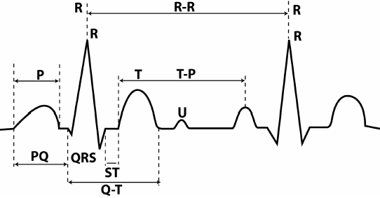
Rice. 7. Teeth, segments and intervals of the ECG.
The parameters of the teeth are the direction (positive, negative, two-phase), as well as the height and width. Since the height of the tooth corresponds to the change in potential, it is measured in mV. As already mentioned, a height of 1 cm on the tape corresponds to a potential deviation of 1 mV (control millivolt). The width of a tooth, segment or interval corresponds to the duration of the phase of a certain cycle. This is a temporary value, and it is customary to denote it not in millimeters, but in milliseconds (ms).
When the tape moves at a speed of 50 mm / s, each millimeter on paper corresponds to 0.02 s, 5 mm to 0.1 ms, and 1 cm to 0.2 ms. It's very simple: if 1 cm or 10 mm (distance) is divided by 50 mm/s (speed), then we get 0.2 ms (time).
Tooth R. Displays the spread of excitation through the atria. In most leads, it is positive, and its height is 0.25 mV, and its width is 0.1 ms. Moreover, the initial part of the wave corresponds to the passage of the impulse through the right ventricle (since it is excited earlier), and the final part - through the left. The P wave may be inverted or biphasic in leads III, aVL, V 1 , and V 2 .
Interval P-Q (orP-R)- the distance from the beginning of the P wave to the beginning of the next wave - Q or R. This interval corresponds to the depolarization of the atria and the passage of the impulse through the AV junction, and further along the bundle of His and its legs. The value of the interval depends on the heart rate (HR) - the higher it is, the shorter the interval. Normal values are in the range of 0.12 - 0.2 ms. A wide interval indicates a slowdown in atrioventricular conduction.
Complex QRS. If P represents atrial work, then the next waves, Q, R, S and T, represent ventricular function, and correspond to different phases of depolarization and repolarization. The combination of QRS waves is called the ventricular QRS complex. Normally, its width should be no more than 0.1 ms. Excess indicates a violation of intraventricular conduction.
Prong Q. Corresponds to depolarization of the interventricular septum. This tooth is always negative. Normally, the width of this wave does not exceed 0.3 ms, and its height is no more than ¼ of the R wave following it in the same lead. The only exception is lead aVR, where a deep Q wave is recorded. In other leads, a deep and widened Q wave (in medical slang - kuishche) may indicate a serious pathology of the heart - an acute myocardial infarction or scarring after a heart attack. Although other reasons are possible - deviations of the electrical axis during hypertrophy of the heart chambers, positional changes, blockade of the legs of the bundle of His.
ProngR .Displays the spread of excitation through the myocardium of both ventricles. This wave is positive, and its height does not exceed 20 mm in the leads from the limbs, and 25 mm in chest leads. The height of the R wave is not the same in different leads. Normally, in lead II, it is the largest. In ore allotments V 1 and V 2 it is low (because of this, it is often denoted by the letter r), then it increases in V 3 and V 4, and again decreases in V 5 and V 6. In the absence of an R wave, the complex takes the form of a QS, which may indicate a transmural or cicatricial myocardial infarction.
Prong S. Displays the passage of the impulse along the lower (basal) part of the ventricles and the interventricular septum. This is a negative prong, and its depth varies widely, but should not exceed 25 mm. In some leads, the S wave may be absent.
T wave. The final section of the ECG complex, showing the phase of rapid ventricular repolarization. In most leads, this wave is positive, but it can also be negative in V 1 , V 2 , aVF. The height of the positive teeth directly depends on the height of the R wave in the same lead - the higher the R, the higher the T. The causes of the negative T wave are diverse - small-focal myocardial infarction, dyshormonal disorders, previous meals, changes in the electrolyte composition of the blood, and much more. The width of the T waves usually does not exceed 0.25 ms.
Segment S-T- the distance from the end of the ventricular QRS complex to the beginning of the T wave, corresponding to the complete coverage of the excitation of the ventricles. Normally, this segment is located on the isoline or deviates slightly from it - no more than 1-2 mm. Large S-T deviations indicate a severe pathology - a violation of the blood supply (ischemia) of the myocardium, which can turn into a heart attack. Other, less serious causes are also possible - early diastolic depolarization, a purely functional and reversible disorder, mainly in young men under 40 years of age.
Interval Q-T- the distance from the beginning of the Q wave to the T wave. Corresponds to ventricular systole. Value the interval depends on the heart rate - the faster the heart beats, the shorter the interval.
ProngU . An unstable positive wave, which is recorded after the T wave after 0.02-0.04 s. The origin of this tooth is not fully understood, and it has no diagnostic value.
ECG interpretation
Heart rhythm . Depending on the source of impulse generation of the conduction system, sinus rhythm, rhythm from the AV junction, and idioventricular rhythm are distinguished. Of these three options, only sinus rhythm is normal, physiological, and the remaining two options indicate serious disorders in the conduction system of the heart.
A distinctive feature of sinus rhythm is the presence of atrial P waves - after all, the sinus node is located in the right atrium. With a rhythm from the AV junction, the P wave will overlap the QRS complex (while it is not visible, or follow it. In idioventricular rhythm, the source of the pacemaker is in the ventricles. At the same time, widened deformed QRS complexes are recorded on the ECG.
heart rate. It is calculated by the size of the gaps between the R waves of neighboring complexes. Each complex corresponds to a heartbeat. Calculating heart rate is easy. You need to divide 60 by the R-R interval, expressed in seconds. For example, the interval R-R equals 50 mm or 5 cm. At a tape speed of 50 m / s, it is equal to 1 s. Divide 60 by 1 and you get 60 heartbeats per minute.
Normal heart rate is in the range of 60-80 beats / min. Exceeding this indicator indicates an increase in heart rate - about tachycardia, and a decrease - about a slowdown, about bradycardia. With a normal rhythm R-R gaps on the ECG should be the same, or approximately the same. Slight difference allowed R-R values, but not more than 0.4 ms, i.e. 2 cm. This difference is typical for respiratory arrhythmias. This is a physiological phenomenon that is often observed in young people. With respiratory arrhythmia, there is a slight decrease in heart rate at the height of inspiration.
alpha angle. This angle reflects the total electrical axis of the heart (EOS) - the general directing vector of electrical potentials in each fiber of the conduction system of the heart. In most cases, the directions of the electrical and anatomical axis of the heart coincide. The alpha angle is determined by the six-axis Bailey coordinate system, where standard and unipolar limb leads are used as axes.
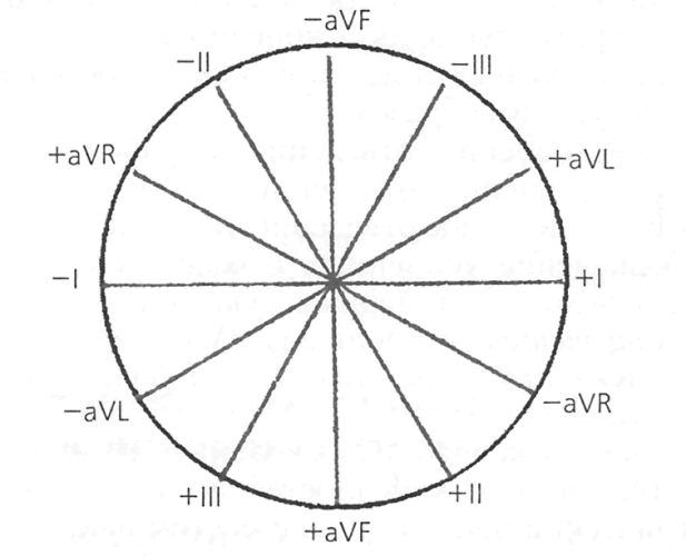
Rice. 8. Six-axis coordinate system according to Bailey.
The alpha angle is determined between the axis of the first lead and the axis where the largest R wave is recorded. Normally, this angle ranges from 0 to 90 0 . In this case, the normal position of the EOS is from 30 0 to 69 0, vertical - from 70 0 to 90 0, and horizontal - from 0 to 29 0. An angle of 91 or more indicates EOS deviation to the right, and negative values of this angle indicate EOS deviation to the left.
In most cases, a six-axis coordinate system is not used to determine the EOS, but they do it approximately, according to the value of R in standard leads. In the normal position of the EOS, the height R is the largest in lead II, and the smallest in lead III.
With the help of an ECG, various violations of the rhythm and conduction of the heart, hypertrophy of the chambers of the heart (mainly the left ventricle), and much more are diagnosed. ECG plays a key role in the diagnosis of myocardial infarction. According to the cardiogram, one can easily determine the duration and prevalence of a heart attack. Localization is judged by the leads in which pathological changes are found:
I - anterior wall of the left ventricle;
II, aVL, V 5 , V 6 - anterolateral, lateral wall of the left ventricle;
V 1 -V 3 - interventricular septum;
V 4 - the apex of the heart;
III, aVF – posterior diaphragmatic wall of the left ventricle.
ECG is also used to diagnose cardiac arrest and assess the effectiveness of resuscitation. When the heart stops, all electrical activity stops, and a solid isoline is visible on the cardiogram. If resuscitation measures (chest compressions, drug administration) were successful, the ECG again displays the teeth corresponding to the work of the atria and ventricles.
And if the patient looks and smiles, and there is an isoline on the ECG, then two options are possible - either errors in the ECG recording technique, or a malfunction of the device. The ECG registration is carried out by a nurse, the interpretation of the data obtained is carried out by a cardiologist or a doctor of functional diagnostics. Although a doctor of any specialty is obliged to navigate in matters of ECG diagnostics.
Theoretical basis
Standard leads
Lead I.
Lead II.
Lead III.
Electrocardiograph
An electrocardiograph is a device that records the potential differences caused by the electrical activity of the heart between points on the surface of the body.
Typical blocks of the electrocardiograph:
1. Input device - a system of electrodes, cables for their connection to the device, devices for fixing the electrodes.
2. Amplifier of biopotentials. The gain is about 1000.
3. Recorder - usually a thermal printer with a resolution of at least 8 dots/mm. 25 mm/s and 50 mm/s tape feed speeds apply
4. LCD - screen with video controller.
5. Central processor.
6. Keyboard.
7. Power supply
8. Calibration block. When it is switched on for a short time, a calibration rectangular pulse with an amplitude of (1 ± 0.01) mV is connected to the amplifier input instead of the patient. If the gain according to clause 2 is within tolerance, then a rectangular pulse with a height of 10 mm is written on the tape
Requirements GOST 19687-89
GOST 19687-89 "DEVICES FOR MEASURING BIOELECTRIC POTENTIALS OF THE HEART" (see Appendix 1) defines the main characteristics of electrocardiographs and electrocardioscopes and methods for their measurement. The main parameters of the devices must correspond to those given in Table 1.
Table 1
| Parameter name | Parameter value |
| 1. Input voltage range U, mV. within 2. Relative voltage measurement error* and, in the ranges: from 0.1 to 0.5 mV, %, no more than 0.5 to 4 mV, %, no more than 3. Nonlinearity, %, within: for electrocardiographs for electrocardioscopes 4. Sensitivity S, mm/mV 5. Relative error of sensitivity setting, %. within 6. Effective channel recording (image) width V, mm, not less than 7. Input impedance Zin, MΩ, not less than 8. Common mode signal attenuation coefficient Kc, not less than: for electrocardiographs for electrocardioscopes input Ush, µV, not more than 10. Time constant, s. not less than 11. Unevenness of the amplitude-frequency characteristic (AFC) in the frequency ranges: from 0.5 to 60 Hz, % from 60 to 75 Hz, % 12. Relative error in measuring time intervals in the range of time intervals from 0.1 to 1.0 s,% no more than 13. Speed of movement of the recording medium (sweep speed) Vn mm/s 14. Relative error of setting the speed of movement of the recording medium (sweep speed),%, within: for electrocardiographs for electrocardioscopes | 0.03 to 5 ±15 ±7 ±2 ±2.5 2.5**; 5; ten; twenty; 40** ±5 40*** 100000 28000 20 3.2 -10 to +5 -30 to +5 ±7 25.50 other values are allowed ±5 ±10 |
* It is allowed not to check during acceptance tests.
** Allowed by agreement with the customer.
*** For wearable devices, values less than 40 mm are allowed upon agreement with the customer.
In the international standard IEC 60601-2-51 “Medical electrical equipment-Part 2-51: Particular requirements for safety, including essential performance, of recording and analyzing single channel and multichannel electrocardiographs”, adopted entirely in the Russian Federation, the requirements are set in SECTION EIGHT - ACCURACY OF OPERATING DATA AND PROTECTION AGAINST HAZARDOUS OUTPUT (see Appendix 2).
Typical electrocardiograph circuit with active common-mode compensation.

Rice. 5. Typical structure of an ECG channel with active compensation for common mode noise.

Rice. 6. The main part of the ECG channel diagram
Cardiograph DIXION ECG-1001a

Patient lead cable

matching device


Back and front panel respectively.
Installation diagram.

Scheme of a matching device for checking the range of recorded signals, sensitivity errors, voltage measurement errors, time interval measurement errors, movement speed errors, calibration signal errors, time constant, frequency response
Conventions circuit elements and their nominal values:
G1 is a special waveform generator;
G2 - rectangular pulse generator;
R1 - 51 kOhm ± 5%;
R2– 100 kOhm ±0.1%;
R3– 100 Ohm ±0.1%;
R4– 51 Ohm ±5%;
R5 - choose to obtain a voltage on R4 ± (300 mV ± 10%) depending on the source voltage;
R8 - 100 Ohm ±5%;
C1 - 47nF ±10%;
Z1 - R1 and C1 connected in parallel;
Z2 - R6 and C2 connected in parallel;
U is a constant voltage source that provides voltage to R4±(300±10%).
Work order
Under the supervision of a laboratory assistant, assemble the scheme of the installation.
Before checking the main parameters, the device is tested for permissible input voltage overloads in each recording channel with a harmonic signal with a range of 1V ÷ 5% and a frequency of 50 Hz ± 5%, applied between the outlet electrodes for at least 10 s. Filters must be turned off. The tests shall not damage the writing mechanism or the electrical circuitry of the instrument.
Set the tape advance speed to 25 mm/s (in the cardiograph menu). This means that when deciphering the records, one millimeter along the tape corresponds to the time t = 1/25 = 0.04 s/mm.
1. Check the relative error of the sensitivity setting by applying a rectangular signal of 5 Hz ±5% and an amplitude of 1 V ±2% to the input of the device and changing the gain (20, 10, 5).
For this:
· From the signal library (More Function button) select a rectangular signal, CardTest01_05_1(0.33Hz), shown in Figure 12.3 and set the frequency to 0.33 Hz.
· On the generator panel, set the signal amplitude to 2 V.
· On the cardiograph, select the sensitivity equal to 5mm/mV using the SENS button. The following sensitivity levels are available: ×1(10mm/mV) → ×2(20mm/mV) → AGC→ · 25 (2.5mm/mV) → · 5(5mm/mV)).
· Trigger the signal with the RUN button.
· Repeat everything, setting the amplitude to 1V, and the sensitivity to 10mm/mV. And then set the amplitude to 0.5V and the sensitivity to 20mm/mV.
· Using a ruler and a compass, we measure the deviation of the amplitude, the deviation is ± 5%.
We put the results in a table.

2. To check the unevenness of the frequency response, apply a harmonic signal to the input of the device in accordance with scheme 7.1.
The uneven frequency response in percent is calculated by the formula: δ 1 = * 100,
where h o is the size of the image span of the sinusoid on the record at a reference frequency of 10 Hz, mm.
h max - the size of the image swing of the sinusoid on the record, which is maximally different from h about in the positive or negative side, mm.
To check the frequency response of the voltage measurement error, it is recommended to use the complex test signals of the PCSGU-250 generator, shown in Fig.12. (1 and 2 signal)
For this:
· Select a signal from the signal library, CardTest10_20_30_40_50_60_75_100(0.5Hz).
· Set the frequency to 0.5 Hz and the amplitude to 2V.
· Set the sensitivity of the cardiograph to 10mm/mV.
We record the signal.
· Using a ruler and a compass, we measure h o (for a 10 Hz burst of signals) and h max 1 (for a 60 Hz burst of signals) and h max 2 (for a 75 Hz burst of signals.
· We carry out the calculation according to the formula for 60 and 75 Hz signals.
· We repeat all the steps for the CardTest05_2_10_25(0.25Hz) signal, setting the amplitude to 2V, the frequency to 0.25 Hz.
We measure h o for a burst of signals 0.5 Hz and h max for a burst of signals 10 and 25 Hz, h max 1 (for 10 Hz) and h max 2 (for 25 Hz)
The results are entered into a table.
The frequency response deviations are as follows: in the first signal for a 60Hz burst "-10%", for a 75Hz burst - "30%". In the second signal ±5%.

Fig.12. Complex test signals used in the verification of electrocardiographs.
3. Check the time constant in each channel at a sensitivity of 5 mm / mV by applying a rectangular signal with a swing of 4 mV ± 3% to the input of the device for less than 5 s. Determine the time constant from the record as the decay time of the signal to the level of 0.37 according to the drawing, excluding emissions.
The image of the transient response on the recording for each channel should be monotonous, facing the zero line.
· We select a rectangular signal with a swing of 4mV.
· Set the sensitivity on the cardiograph to 5mm/mV.
We record the signal.
Using a ruler, measure the maximum amplitude (A), then draw horizontal line at the level of 0.37A to the intersection with the signal line, and measure τ as shown in the figure below.

Table of results when measuring sensitivity error
Table of results when checking the unevenness of the frequency response
Table of results when checking the time constant
| τ |
Conclusions:
Theoretical basis
Integral electric heart vector(IEVS) is the vector sum of dipole moments of current dipoles over the entire volume of the heart. During heart contraction IEVS changes both in magnitude and in direction, which causes the propagation of electromagnetic energy in space.
Standard leads
This energy, spreading from the heart in many directions, causes the appearance of surface potentials on the skin at different points. This potential difference, called a lead, can be recorded.
Lead provides an estimate of the electrical activity of the heart between two points (poles). Each lead consists of a positive (+) pole, or active electrode, and a negative (-) pole. An imaginary line runs between the positive and negative poles, representing the axis of abduction. Since the leads allow you to measure the electrical potential of the heart from different positions, the signals recorded by these leads give their own characteristic curve for each lead.
The direction of movement of the electrical signal determines the shape of the ECG waves. When it coincides with the direction of the axis of abduction and is directed towards the positive pole, the line on the ECG deviates upward (“positive deviation”). When the electric current is directed from the positive pole to the negative, it deviates downward from the isoline ("negative deviation"). When the direction of the current is perpendicular to the axis, the ECG waves are in any direction or may be low. If there is no electrical activity or too little to measure, a straight line appears on the ECG, which is referred to as an isoelectric deviation.
In a plane passing through the heart vertically from apex to base, electrical currents are viewed in the direction of the heart from the front. The frontal plane is provided by six limb leads (I, II, III, aVR, aVL, aVF) (Fig. 1).
In a plane passing horizontally through the middle of the heart, the direction of electric currents is considered from top to bottom. This approach is provided by six chest leads (V 1 -V 6) (Fig. 2).
Rice. 2. Horizontal plane
leads I, II and III (according to Einthoven). These three leads are called the standard, or bipolar, limb leads.
To record standard limb leads, electrodes are placed on the right forearm, left forearm, and left leg. The fourth electrode is placed on the right shin, it is used as a ground to stabilize the ECG recording and does not affect the characteristics of the electrical signals recorded on the ECG.
These leads are called bipolar because each has two electrodes that provide a simultaneous recording of the electrical currents of the heart going towards the two limbs. Bipolar leads allow you to measure the potential between the positive (+) and negative (-) electrodes.
Lead I. Registers electrical currents between the right (red electrode) and left forearms (yellow electrode).
Lead II. Registers electrical currents between the right forearm (red electrode) and left leg (green electrode).
Lead III. Registers electrical currents between the left leg (green electrode) and left forearm (yellow electrode).
The electrode on the right forearm is always considered as a negative pole, on the left leg is always considered as a positive one. The electrode on the left forearm can be either positive or negative depending on the lead: in lead I it is positive, and in lead III it is negative.
When the current is directed towards the positive pole, ECG wave directed upward from the isoelectric line (positive). When the current goes to the negative pole, the ECG wave is inverted (negative). In lead II, the current travels from the negative to the positive pole, which is why the waveforms on a regular ECG are pointing up.
The concept of Einthoven's triangle.
Placement of electrodes for recording leads I, II and III, as shown in fig. 3 forms the so-called Einthoven triangle. Each side of this equilateral triangle between the two electrodes corresponds to one of the standard leads Einthoven believed that the heart is located in the center of the electric field generated by it. Therefore, the heart is considered as the center of this equilateral triangle. Einthoven's triangle produces a figure with a three-axis coordinate system for standard leads I, II, and III.

Rice. 3. Einthoven's triangle
Einthoven's law states: the sum of the electrical potentials recorded at any time in leads I and III is equal to the electrical potential recorded in lead P. This law can be used to detect errors made when applying electrodes, to find out the reasons for recording unusual signals in one of the three standard leads, and to evaluate serial ECGs.
Leads aVR, aVL and aVF (according to Goldberg). These three leads have common name reinforced unipolar limb leads.
These leads use the same electrode positions as standard leads I, II, and III, i.e. the electrodes are fixed on the right forearm, left forearm, and left calf. The electrode placed on the right shin is not used when recording signals in these leads.
In leads aVR, aVL and aVF, the difference in electrical potentials between the limbs and the center of the heart is examined. They are called single-pole because only one electrode is used to register an electrical signal; the center of the heart is always neutral, so a second electrode is not required. The designation of augmented limb leads comes from the first letters of the English words "a" - augmented (reinforced), "V" -voltage (potential), "R" -right (right), "L" -left (left), "F" -foot (foot).
In connection with the above, all electrodes in these leads are positive. The negative electrode is obtained by adding the signals of leads I, II and III, the algebraic sum of which is equal to zero.
These leads are also called enhanced because the amplitude of the complexes is increased by 50% compared to the standard leads. Recording of enhanced leads is more convenient for interpretation.
The ratios underlying the operation of the electrocardiograph:
UI= Uin(L)-Uin(R);
UII= Uin(F)-Uin(R);
UIII= Uin(F)-Uin(L);
UaVR=Uin(R)-(Uin(L)-Uin(F))/2;
UaVL=Uin(L)-(Uin(F)-Uin(R))/2;
UaVF=Uin(F)-(Uin(L)-Uin(R))/2;
UVi= Uin(Ci)-(Uin(R)+Uin(L)+Uin(F))/3, where i=1,2,…,6.
Leads V1-V6 (according to Wilson). These six leads are called unipolar cardiac or chest leads. They are denoted by the letter V, and the points of removal of positive potentials j (and the corresponding wires of the lead cable) - by the letter C with a number corresponding to the position of the electrode (Fig. 4). The negative potential is taken from the point, the potential of which is formed in accordance with the relation (j R + j L + j F)/3.
The electrodes are located at the following points:
C(V)1 - in the fourth intercostal space along the right edge of the sternum (red electrode);
C(V)2 - in the fourth intercostal space along the left edge of the sternum (yellow electrode);
C(V)3 - in the middle of the line connecting points V2 and V4 (green electrode);
C(V)4 - in the fifth intercostal space along the left mid-clavicular line (brown electrode);
C(V)5 - in the fifth intercostal space on the left anterior axillary line (black electrode);
 |
C(V)6 - in the fifth intercostal space on the left mid-axillary line (purple electrode).
Rice. 4. Leads according to Wilson
In the chest leads, the electrical potential difference between the electrodes placed on the chest and the central terminal is measured. The chest electrodes in any of the V leads are always positive. The negative electrode is obtained by adding the signals of leads I, II and III, the algebraic sum of which is equal to zero.
In 2002 published an editorial "10 Greatest Discoveries in Cardiology of the 20th Century". These included angioplasty and open operation on the heart. However, undoubtedly, the first method on this list is electrocardiography, and next to it is the name of the Dutchman Willem Einthoven, the creator of the first common method of instrumental non-invasive diagnostics that each of us encountered. The Nobel Committee appreciated the invention and with the wording "for his discovery of the technique of electrocardiography" presented Einthoven with the prize.
Figure 1. Augustus Desiree Waller and his dog Jimmy.
To be completely accurate, then, of course, it was not Einthoven who took the first electrocardiogram (ECG) in history. But rating Texas Heart Institute Journal still fair - it was absolutely nothing clear. And the "Dutch" of our hero can be called, but it can be done differently. However, everything is in order.
If we argue according to the principle “state N is the birthplace of elephants”, Rutherford, for example, will be the first New Zealand Nobel laureate, and Willem Einthoven - the first Nobel laureate of Indonesia. Because he was born on the island of Java, in the city of Semarang, now the fifth largest city in Indonesia. Then it was the Dutch East Indies, nobody heard about the state of Indonesia, because more than 80 years remained before the recognition of its independence.
With the origin of Einthoven, too, everything is intricate: he is a descendant of Jews expelled from Spain. The surname appeared under Napoleon, who in his Code specified that all citizens of his empire, which included Holland, had surnames. Einthoven's great-uncle chose a slightly garbled name for the city where he lived (I hope I don't need to mention which one).
The father of the future Nobel laureate was a military doctor, Jacob Einthoven, who, unfortunately, could not provide for his own health. In 1866 he died of a stroke, and four years later (Willem was already 10 at the time) his family moved to Utrecht. Of course, there was not much wealth in the family - his mother was left alone with three children. Willem decided to follow in his father's footsteps - partly out of vocation (medicine), partly out of need. The fact is that by concluding a military contract, he was able to study at the medical faculty of Utrecht University for free.
In his student years, Willem was a very athletic person, regularly stated that in studies one should “not let the body die”, he was an excellent fencer and rower (the latter, again, forcedly, because he broke his wrist and took up rowing to restore the functionality of the hand). Yes, and Einthoven's first work on medicine was devoted to the mechanism of work elbow joint, equally important to both the rower and the fencer. In this work, perhaps, the duality of Einthoven's talent has already manifested itself: an excellent knowledge of anatomy and physiology and an interest in the physical principles of work human body. In this case, mechanics. But then there were works on optics, and, of course, on electricity.

Figure 2. Lippmann capillary electrometer.
Further, our hero was very lucky. True, Adrian Heinsius, professor of physiology at the University of Leiden, was unlucky: he died. And the young Einthoven, a quarter of a century old, instead of serving in the medical corps, got a professorship at a not very recent European university. This happened in 1886, and since then, for more than 41 years, Einthoven worked in Leiden - until his death in 1927.
Einthoven was also actively involved in ophthalmology - his doctoral thesis was called "Stereoscopy through color differentiation." Later, very interesting works "A simple physiological explanation of various geometric-optical illusions", "Accommodation of the human eye" and others were published. However, most of the time the young researcher was engaged in the physiology of respiration. Including the work of nerve impulses in the mechanism of breath control.
But then the First International Congress on Physiology arrived in time - the most important event in world medicine (Basel, 1889). There was an epoch-making meeting with Augustus Waller(Fig. 1), who was the first in the world to show that it is possible to record the electrical impulses of the heart without opening the body of a living organism (1887). That the human body itself could produce electricity was a very new idea in physiology.
In Basel, Waller showed his work with own dog Jimmy. It is Waller who should be called (and is called) the discoverer of the ECG.
True, I must say that Waller's cardiograms were terrible. He recorded pulses using a capillary electrometer (by the way, developed by the Nobel laureate in physics in 1908 and one of the inventors of color photography, Gabriel Lippmann) (Fig. 2).

Figure 3. Einthoven string galvanometer.

Figure 5. Einthoven's triangle.
In this device, electrical impulses from the heart fell on a capillary with mercury, the level of which varied depending on the current strength. But by itself, mercury did not change position instantly, but had some inertia (mercury is a very heavy liquid). The result was porridge. Moreover, recording heart impulses is an interesting task, but here any scientist should be able to answer the most main question- "and what?"
For five years (from 1890 to 1895) Einthoven was engaged in improving the technology of capillary electrometry and along the way created a normal mathematical apparatus for processing "porridge". Something began to turn out, but still the device was unreliable, inaccurate and cumbersome. However, it cannot be said that these years were wasted: in 1893, at a meeting of the Netherlands Medical Association, the term "electrocardiogram".
However, it was not possible to obtain a normal cardiogram by the capillary method. And in 1901, Willem Einthoven made his own device - string galvanometer, and the first article that a cardiogram was recorded on it, he published in 1903 (the edition is dated 1902).
Its main part was a quartz string - a thread of quartz 7 microns thick (Fig. 3). It was made in a very original way: an arrow, to which a heated quartz fiber was attached, was fired from a bow (we add that in the same way, 20 years later, young researchers Nikolai Semenov and Pyotr Kapitsa received ultra-thin capillaries in the newly created Leningrad Phystekh). This thread, when electrical impulses hit it, was deflected in a constant magnetic field. To fix the deviation of the filament, photographic paper was moved parallel to it during measurements, onto which a shadow from the filament was projected using a system of lenses (Fig. 4).

Figure 6. Waves and intervals of the cardiogram.
It is interesting how a temporary coordinate grid was applied to the first cardiograms (now paper for cardiograms immediately contains a grid, but Einthoven had photographic paper!). The grid was applied using shadows from the spokes of a bicycle wheel rotating at a constant speed.
The Dutchman did not live long as a laureate - two years after his Nobel lecture, he died of stomach cancer. The saddest thing is that, despite the openness of his laboratory (it often had guests), neither students nor scientific school remained after Einthoven. But there is a laboratory of Einthoven: the laboratory of experimental vascular medicine in his native Leiden is named after him (Leiden University medical Center, LUMC).
And one more interesting observation. The article about Einthoven in the Russian-language Wikipedia is much more detailed and longer than the article in the English-language one, and moreover, it is among the "good" articles (I testify - it's good!). Amazing Fact, but the discoverer of the cardiogram has its own Russian-speaking fans. However, now they have become at least one more.
Literature
- Mehta N.J., Khan I.A. (2002). Cardiology's 10 greatest discoveries of the 20th century. Tex. Heart Inst. J. 29 , 164–71 ;
- Waller A. D. (1887). A demonstration on man of electromotive changes accompanying the heart's beat . J. Physiol. 8 , 229–234 ;
- Einthoven W. (1901). Un nouveau galvanometer. Archives néerlandaises des sciences exactes et naturelles. ". Website of the Polytechnic Museum.