Lenses and their application in working with light. Fresnel lens and its role in motion sensors Flat fresnel lens
The Fresnel lens enlarges the portrait of its creator. (Page from the volume "Physics, Part 2" of the Children's Encyclopedia of the "Avanta +" publishing house).
You can collect light into a narrow beam using a concave mirror (a) or a lens (b), placing the light source at the focal point. At a spherical mirror, it lies at a distance of half the radius of curvature of the mirror.
A converging lens can be thought of as a set of prisms that deflect light rays to a single point - the focus. By repeatedly increasing the number of these prisms, respectively reducing their size, we get an almost flat lens - the Fresnel lens.
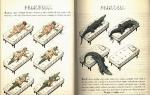
The design of the lighthouse lighting system (Fresnel drawing). The light of the burner F is focused by the lenses L and L" reflected by the mirrors M. The light of the burner propagating downward is reflected in the desired direction by a system of mirrors (shown by a dotted line).
This is what a modern Fresnel lens looks like. Often it is made from a single piece of glass.
The Fresnel lens-ruler focuses the sun's rays no worse, and even better (because it is larger) than a conventional glass lens. The sun's rays collected by her instantly set fire to a dry pine board.
One of the creators of the wave theory of light, the outstanding French physicist Augustin Jean Fresnel was born in a small town near Paris in 1788. He grew up as a sickly boy. The teachers considered him stupid: at the age of eight he could not read and could hardly remember the lesson. However, in high school, Fresnel showed remarkable aptitude for mathematics, especially geometry. Having received an engineering education, since 1809 he participated in the design and construction of roads and bridges in various departments of the country. However, his interests and opportunities were much wider than simple engineering activities in the provincial wilderness. Fresnel wanted to do science; he was especially interested in optics, the theoretical foundations of which had just begun to take shape. He studied the behavior of light rays passing through narrow holes, bending around thin threads and the edges of the plates. Having explained the features of the pictures that arise in this case, Fresnel in 1818-1819 created his theory of optical interference and diffraction - phenomena that arise due to the wave nature of light.
At the beginning of the 19th century, European maritime states decided to work together to improve lighthouses - the most important navigation devices of that time. In France, a special commission was created for this purpose, and Fresnel was invited to work in it because of his rich engineering experience and deep knowledge of optics.
The light of the lighthouse should be visible far away, so the lighthouse lantern is raised to a high tower. And in order to collect its light into rays, the lantern must be placed at the focus of either a concave mirror or a converging lens, and a rather large one at that. The mirror, of course, can be made of any size, but it gives only one beam, and the light of the beacon must be visible from everywhere. Therefore, sometimes one and a half dozen mirrors were placed on lighthouses with a separate lantern at the focus of each mirror (see Science and Life, No. 4, 2009, article). Several lenses can be mounted around one lamp, but it is almost impossible to make them of the necessary - large - size. In the glass of a massive lens, there will inevitably be inhomogeneities, it will lose its shape under the influence of its own gravity, and due to uneven heating it may burst.
New ideas were needed, and the commission, inviting Fresnel, made right choice: in 1819 he proposed the design of a compound lens, devoid of all the shortcomings inherent in a conventional lens. Fresnel probably reasoned like this. A lens can be represented as a set of prisms that refract parallel light rays - deflect them at such angles that after refraction they converge at a focal point. This means that instead of one large lens, you can assemble a structure in the form of thin rings from separate triangular prisms.
Fresnel not only calculated the shape of the ring profiles, he also developed the technology and controlled the entire process of their creation, often acting as a simple worker (subordinates turned out to be extremely inexperienced). His efforts have yielded brilliant results. “The brightness of the light that the new device gives surprised the sailors,” Fresnel wrote to friends. And even the British - longtime competitors of the French at sea - admitted that the designs of French lighthouses turned out to be the best. Their optical system consisted of eight square Fresnel lenses with a side of 2.5 m, which had a focal length of 920 mm.
190 years have passed since then, but the designs proposed by Fresnel remain an unsurpassed technical device, and not only for lighthouses and river buoys. Until recently, glasses of various signal lights, car headlights, traffic lights, parts of lecture projectors were made in the form of Fresnel lenses. And just recently, magnifiers appeared in the form of rulers made of transparent plastic with barely noticeable circular grooves. Each such groove is a miniature annular prism; and together they form a converging lens, which can work both as a magnifier, magnifying the object, and as a camera lens, creating an inverted image. Such a lens is able to collect the light of the Sun into a small speck and set fire to a dry board, not to mention a piece of paper (especially black).
The Fresnel lens can be not only collecting (positive), but also scattering (negative) - for this you need to make ring prisms-grooves on a piece of transparent plastic of a different shape. Moreover, a negative Fresnel lens with a very short focal length has a wide field of view, in which a piece of landscape is placed in a reduced form, two to three times larger than it covers the naked eye. Such "minus" plates-lenses are used instead of panoramic rear-view mirrors in large cars such as minibuses and station wagons.
The edges of miniature prisms can be coated with a mirror layer - for example, by spraying aluminum. Then the Fresnel lens turns into a mirror, convex or concave. Manufactured using nanotechnology, such mirrors are used in telescopes operating in the X-ray range. And molded in flexible plastic, visible-light mirrors and lenses are so easy and cheap to make that they are produced literally miles in the form of ribbons for window dressing or curtains for bathrooms.
There have been attempts to use Fresnel lenses to create flat lenses for cameras. But technical difficulties stood in the way of the designers. White light in a prism is decomposed into a spectrum; the same happens in the miniature prisms of a Fresnel lens. Therefore she has significant disadvantage- the so-called chromatic aberration. Because of it, a rainbow border appears on the edges of the images of objects. In good lenses, the border is eliminated by placing additional lenses (see "Science and Life" No. 3, 2009, article). The same could be done with a Fresnel lens, but then a flat lens would no longer work.
In the old days, approaching the shore for sailors was the most dangerous part of their journey. Due to adverse climatic conditions, shallows or coastal rocks could cause a shipwreck. Sailors were saved by lighthouses, the best navigational structures of that time. For a long time, fires were simply kindled on their peaks, later they served as light sources until they began to use electricity. In the 19th century, the Fresnel lens became the life-saving light, making the light of the lighthouse the brightest and most visible from afar.
The composite compound lens was created by Augustin Fresnel, a French physicist, creator of the wave theory of light. The Fresnel lens is made up of individual small thickness concentric rings adjacent to each other and forming a cylinder with a light source inside. In cross section, the rings have the shape of prisms. Each of the rings collects light into a parallel narrow beam of rays that radiates from the center. When the cylinder rotates around the light source, the rays of light extend to the very horizon. The color of the rays, their number, the time interval between them make up a special unique handwriting of the lighthouse. A summary with the characteristics of various lighthouses was available on board the ships, and it was from it that the sailors found out which lighthouse was in front of them.
Fresnel lenses installed on lighthouses were a major step in equipping them with powerful light sources. These complex compound lenses made it possible to increase the concentration of light intensity up to 80,000 candles. Prior to Fresnel's invention, it was possible to focus the light of a burning wick or lantern only by placing the lantern in a focus of a sufficiently large diameter or a concave mirror. For these purposes, a one-piece optical element of a large size was needed, which, under the influence of its own gravity, could burst. Therefore, dozens of concave mirrors were used, each with a separate lantern at its focus. This decision was inconvenient.

The composite Fresnel lens helped to achieve an increase in the intensity of light, its concentration in a given direction. The assembly of individual optical elements did not reflect light, but worked in transmission, rotating around a light source that emitted constant intensity in all directions.
Since then, Fresnel designs have remained an unsurpassed technical device, used not only for river buoys and lighthouses. In the form of Fresnel lenses, glasses of various signal lights, traffic lights, car headlights, parts of lecture projectors were first made. Then loupes were created in the form of rulers made of inconspicuous circular grooves, each of which was a miniature annular prism, and in general they were a converging lens. The resulting lens is used as a magnifying glass to magnify an object, like a camera lens that creates an inverted image.
Over time, the scope of Fresnel lenses has expanded significantly. It includes the development of photographic equipment, various lighting devices, tracking sensors for security systems, and an energy concentrator for mirrors used in telescopes. The optical properties of lenses are also used in the field of multimedia. For example, DNP, the largest manufacturer of high-tech projection screens, creates Supernova screens based on the lens. And in rear projection screens, not only the Fresnel lens is used, but also other optical technologies, which allows you to get the most unique display means.

Depending on the field of application, the lenses may have different diameters and vary in type. There are two types of lenses: annular and waist. The first are designed to direct the flow of light rays in one direction. Ring lenses have found use in manual work with small details, replacing conventional magnifiers. Waist lenses capable of transmitting beams of light in any given direction are used in the industrial sector.
The Fresnel lens can be positive (collecting) and negative (diffusing). A negative polyvinyl lens with a short focus markedly enlarges. It is known as a parking Fresnel lens. The wide field of view it gives allows you to see obstacles below the vehicle that are not in the field of view of the side mirrors or the rearview mirror. Such a lens greatly facilitates maneuvering when parking, towing a trailer and avoiding collision with playing children, animals or other objects.
The Fresnel lens has become a multifunctional tool, its invention has played an important role in the development of the technological field.
Transverse section
(1) Fresnel lenses and
(2) ordinary lens
Fresnel lens- a complex composite lens, formed by a set of concentric rings of relatively small thickness, adjacent to each other. The section of each of the rings has the shape of a triangle, one of the sides of which is curvilinear, and this section is a section element of a solid spherical lens. Proposed by Augustin Fresnel.
Fresnel lenses are ring and belt. Annular ones concentrate the luminous flux in one direction, belt ones in all directions in a certain plane.
The diameter of a Fresnel lens can range from fractions of a centimeter to several meters.
Application
Creating a parallel beam of light with a Fresnel lens (located in the center)
Fresnel lenses are applied:
Acoustic Fresnel lenses (more precisely, acoustic Fresnel zone plates made of sound-absorbing materials) are used in acoustics to form a sound field.

Fresnel magnifier the size of a credit card

Closeup of the surface of a Fresnel lens.

Not so long ago, I noticed a car on the rear window of which an incomprehensible small lens was pasted, I did not attach any importance to this, but it stuck in my head. Then I saw the same thing again, but on a minivan, and, to my delight, the owner of the table next to his car, my question - what is it, was answered by the Fresnel lens. highly recommend, they say it helps a lot. Let's take a closer look at what kind of device it is and why it can really easily replace parking sensors.
✔ FEATURESDimensions: 200mm x 250mm
Thickness: 1mm
Material: optical acrylic
Negative focal length:-300 mm
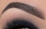
Viewing Angle: up 13º, sides 25º, down 27º
Application: significantly increases the viewing angle; mounted on the rear window of minibuses, station wagons, SUVs, jeeps, vans; on the side windows of trucks.
✔ PACKAGING AND COMPLETE SETArrived in a regular cellophane bag.
Inside of which was a cardboard box. 
On the back of which the characteristics are painted and the principle of operation of the lens is schematically displayed. 
Inside, so that the lens would not be scratched, the seller carefully wrapped it in a piece of paper. 

To do this, let's turn to Wikipedia, which clearly describes what a Fresnel lens is.
The Fresnel lens is a complex composite lens. It is formed by a combination of separate concentric rings of relatively small thickness, adjacent to each other. The section of each of the rings has the shape of a triangle, one of the sides of which is curvilinear, and this section is an element of the section of a continuous spherical lens. Proposed by Augustin Fresnel.
This design provides a small thickness (and hence weight) of the Fresnel lens even with a large angular aperture. The sections of the rings near the lens are constructed in such a way that the spherical aberration of the Fresnel lens is small, the rays from a point source placed at the focus of the lens, after refraction in the rings, come out in an almost parallel beam (in the annular Fresnel lenses). #1 is a regular lens, and #2 is a sectioned Fresnel lens. 
This effect is clearly visible in this photo. There are small "growths" 
The lens itself is made of acrylic, strong enough, I didn’t try to tear it, but it is not afraid of folds and active rubbing of bubbles under it. 
At the bottom there is an inscription Rearguard, but on the top TOP, so that they would not be confused during the “stickers” in the car. 
The lens size is 20cm x 25cm. There are probably more, but I think it's best option.

✔ OPERATING PRINCIPLEIf the object is in the center of the lens, then it appears smaller and farther than it actually is.

Vows on the sides of the lens also fall into the focus of the lens. 

The lens is completely transparent and does not interfere with the view. 
✔ INSTALLATION TO AUTOWe have an ordinary car, a hatchback.

Gently wipe the glass inside clean. 
We disperse all the pimples with a rag. 
This is what the finished version looks like. 
Here, 30-40 centimeters from the bumper, there is a small car fire extinguisher. And here there is a gopher and you can see it. 
This is what it looks like in the rearview mirror. 
✔ FRESNEL LENS TESTS IN AUTOPay attention to how visible the billboard is located in the distance.

The lens can be re-glued almost an infinite number of times, we wet, press and expel bubbles. 
I drive into the tunnel, the camera does not transmit the photo clearly, but the car can be seen well. 
And now pay attention, the car is almost in the blind zone, and it is still fully visible in the lens. 
Some panorama. 

Pay attention to how much "space" the lens shows behind the car. 
"Tavria" is already entering the blind zone, and in the lens it is still fully displayed. 
Let's conduct a small test, behind the car I put a small fire extinguisher already known from the photo above, which is not visible, but it can break the bumper. 
And this is how it is seen in the lens. In fact, when this happens in motion, it is seen much better, since the object simply begins to move closer, and does not stand still. 
Here, for example, from about 3 meters, I’ll clarify in the rear window, I still don’t see it, but through the side mirrors in sunlight, the object is easy to miss, due to its small size. 

Well, this is what my yard looked like before installing the lens. 
And that's how my horizons expanded thanks to her. 
Be in - videos always come out faster!
I did not expect that this piece of plastic would be such a useful car. The blind spots disappeared almost completely, not a single parking sensor sees the column, but here everything is perfectly visible even from 50 centimeters. I highly recommend to owners of minivans and station wagons. Well suited as an original gift to the motorist and yourself. Even the wife already praises and parks almost close to the garage wall, not being afraid to damage the rear bumper. I frankly regret that I didn’t buy this thing a couple of years ago, when I ran into a concrete block with my back, which is stubbornly invisible in the mirrors, a bumper for replacement and painting, and the issue price was not $ 4 ...
And its main value, ease of installation and the complete indifference of thieves, who quite often pick out rear-view cameras.
A lens made up of concentric rings of small thickness adjacent to each other
Animation
Description
The Fresnel lens is one of the first (if not the first historically) devices based on the diffraction of light. Despite its antiquity, it has not lost its practical significance to this day. The skeletal diagram of the physical idea on which its operation is based is shown in fig. one.
Scheme for constructing Fresnel zones for an infinitely distant observation point (plane wave)

Rice. one
A rigorous consideration of this principle of action requires a rather cumbersome and not quite “transparent” mathematical apparatus for a qualitative understanding. Therefore, in the present short description we will confine ourselves to a qualitative presentation, based on simple geometric “pictures” - which nevertheless makes it easy to understand the basic physical principles of the product. For the same readers who require a more fundamental consideration, we advise you to refer to the cited literature.
Let a point source of optical radiation of wavelength l be located at point O. Naturally, like any point source, it emits a spherical wave, the wave front of which is shown in the figure as a circle. Let's set ourselves a noble goal to somehow "remake" this wave into a flat one, propagating along the dotted axis. Several wavefronts of this “projected” wave, separated by l/2, are shown in Figure 1.
To begin with, we note the following. We want to “construct” a plane wave from an existing spherical wave in free space. Therefore, in accordance with the Huygens-Fresnel principle, only electromagnetic oscillations in the existing one can serve as the “sources” of our projected wave. We are not satisfied with the spatial distribution of the phase of these oscillations, that is, the wave front (spherical) of the original wave. Let's try to fix it.
Action one: note that from the point of view of the secondary Huygens-Fresnel waves (which are spherical) a spatial displacement of an entire wavelength in any direction does not change the phase of the secondary sources. Therefore, we can afford, for example, to “break” the wavefront of the original wave, as shown in Fig. 2.
Equivalent phase distribution of secondary radiators in space

Rice. 2
Thus, we have “disassembled” the original spherical wavefront into “ring parts” number 1, 2... and so on. The boundaries of these rings, called Fresnel zones, are determined by the intersection of the wave front of the original wave with a sequence of wave fronts of the “projected wave” displaced relative to each other by l/2. The resulting picture is already significantly “simpler”, and represents 2 slightly “rough” flat secondary emitters (green and red in Fig. 2), which, however, to the greatest regret, cancel each other out due to the mentioned half-wave mutual displacement.
So, we see that the Fresnel zones with odd numbers not only do not contribute to the fulfillment of the task, but even actively harm. There are two ways to deal with this.
The first method (amplitude Fresnel lens). And let's just geometrically close these harmful odd zones with opaque rings. This is how it is done in large-sized focusing systems of sea lighthouses. Of course, this will not achieve ideal beam collimation. We see that the remaining, green, part of the secondary emitters, firstly, is not completely flat, and secondly, it is discontinuous (with zero dips in the place of the former odd Fresnel zones). Therefore, the strictly collimated part of the radiation (and its amplitude is nothing more than the zero two-dimensional Fourier component of the spatial distribution of the phase of green emitters along a plane wavefront with zero offset, see Fig. 2) will be accompanied by wide-angle noise (all other Fourier components except for the zero ). Therefore, the Fresnel lens is almost impossible to use for imaging - only for the collimation of radiation. However, the collimated part of the beam will nevertheless be much more powerful than in the absence of the Fresnel lens, since we have at least got rid of the negative contribution to the zero Fourier component from the odd Fresnel zones.
The second method (phase Fresnel lens). Let's now make the rings covering the odd Fresnel zones transparent, with a thickness corresponding to the additional phase shift l /2 . In this case, the wave front of the “red” secondary radiators will shift and become “green”, see fig. 3.
Wave front of secondary emitters behind a phase Fresnel lens

Rice. 3
In other words, we managed to make the initially harmful contribution to the zero Fourier component from the odd Fresnel zones into a useful one by changing its sign due to the half-wave phase shift. This approach is used in smaller Fresnel lenses, in particular in the backlight collimation lenses used in standard lecture "transparency" projectors on the screen.
Actually phase Fresnel lenses have two versions. The first one is a flat substrate with deposited half-wave layers in the regions of odd Fresnel zones (a more expensive option). The second is a three-dimensional turning part (or even polymer stamping on a once-made matrix, like a gramophone record), made in the form of a “stepped conical pedestal” with a half-wavelength step of the phase incursion.
Thus, Fresnel lenses make it possible to cope with the collimation of beams with a large transverse aperture, while at the same time being flat parts of low weight and relatively low manufacturing complexity. An equivalent lighthouse glass lens weighs half a ton and costs slightly less than an astronomical telescope lens. The point here is that at such scales of the product, the main difficulty is no longer in the processing of the lens surface, but in obtaining a sufficiently optically homogeneous initial glass casting. Therefore, Fresnel lenses are one of the few examples scientific development, which found an immediate and wide practical use(this is at the beginning of the nineteenth century, then!), And “not withdrawn from service” for 2 centuries now.
Let us now turn to the question of what happens when the light source is displaced along the axis relative to the Fresnel lens, which was originally designed to collimate the source radiation in position O (Fig. 1). The initial distance from the source to the lens (that is, the initial curvature of the wavefront on the lens) we agree in advance to call the focal length F by analogy with a conventional lens, see Fig. four.
Constructing an Image of a Point Source with a Fresnel Lens

Rice. four
So, in order for the Fresnel lens to continue to be a Fresnel lens when the source is shifted from position O to position A, it is necessary that the boundaries of the Fresnel zones on it remain the same. And these boundaries are the distances from the axis at which the wave fronts of the incident and “projected” waves intersect. The initially incident one had a front with a radius of curvature F , while the “projected” one was flat (red in Fig. 4). At a distance h from the axis, these fronts intersect, setting the boundary of one of the Fresnel zones, MN=n l /2, n is the number of the zone starting at this distance from the axis.
When the source moved to point A, the radius of the incident wavefront increased and became R 1 (blue in the figure). So we need to come up with a new wavefront surface, such that it intersects with the blue one at the same distance h from the axis, giving the same MN on the axis itself. We suspect that such a surface of the projected wave front can be a sphere with radius R 2 ( green color on the image). Let's prove it.
The distance h is easily calculated from the “red” part of the figure:
 (1)
(1)
Here we have neglected the small square of the wavelength compared to the square of the focus, an approximation that is completely analogous to the parabolic approximation in deriving the usual formula thin lens. On the other hand, we want to find the new boundary of the nth Fresnel zone as a result of the intersection of the blue and green wavefronts, let's call it h 1 . Based on the fact that we require the same length of the segment MN :
 (2)
(2)
Finally, requiring h=h 1 , we get:
This equation is the same as the usual thin lens formula. Moreover, it does not contain the number n of the considered boundary of the Fresnel zones, and therefore, it is valid for all Fresnel zones. Thus, we see that the Fresnel lens can not only collimate beams, but also build images. True, it must be borne in mind that the lens is still stepped, and not continuous. Therefore, the image quality will be markedly degraded by the admixture of the higher Fourier components of the wavefront discussed at the beginning of this section. That is, the Fresnel lens can be used to focus radiation to a given point, but not for precision imaging in microscopic and telescopic devices.
One last note. All of the above referred to monochromatic radiation. However, it can be shown that by careful choice of the diameters of the rings discussed, a reasonable quality of focus can be achieved for natural light as well. The corresponding mathematics is quite complicated, so let's focus on the last verbal statement.
Timing
Initiation time (log to -15 to -13);
Lifetime (log tc 15 to 15);
Degradation time (log td -15 to -13);
Optimal development time (log tk from -1 to -1).
Diagram:

Technical realizations of the effect
Technical implementation of effects
The technical implementation of the effect is quite simple. A spherical wave from a point source (simply a divergent beam of a helium-neon laser after focusing with a lens with a focal length of 3 cm, a point source is a focal beam waist) falls normally on a glass screen, removed at a distance of about 1-2 meters. The circles of the boundaries of the Fresnel zones are marked on the screen (the inner one has a diameter of about 3 mm), and the odd zones are painted over with black ink. In this case, the transmitted beam is collimated into an approximately parallel one.
Applying an effect
Fresnel lenses, both phase and amplitude, are widely used in technology for collimating large aperture light beams, for which the use of conventional spherical lenses and mirrors is difficult. Examples have been discussed above in the content section.
Literature
1. Sivukhin D.V. General course of physics. Optics.- M.: Nauka, 1985.
2. Landsberg G.S. Optics. - M.: Nauka, 1976.
3. Physics. Big Encyclopedic Dictionary.- M.: Big Russian Encyclopedia, 1999.- P.90, 460.
Keywords
- interference
- diffraction
- fresnel zone
- Huygens-Fresnel principle
- focal length
- collimation
- image
- wavelength
Sections of natural sciences: